Shafts, Wheels and Adapters
The construction kit features a system of printable shafts. In addition to the shafts that are native to the kit, many different motors have their own shaft sizes – driveshafts that need either to be reduced or directly connected with pins. In this article, we describe the basic variants and how to work with them.
Native Shafts
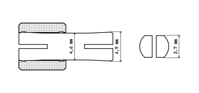
As described here, the shafts have a diameter of 4.3 mm at their weakest point and a flattened shaft width of 3.6 mm. This corresponds to the driveshafts of motors, which have a diameter of 4.5 mm and a flattening of 3.8 mm.
The dimensions of the shafts are chosen so that they can easily rotate in the standard construction kit holes. The kit features several types of shafts that can be used as needed.
- Shaft with a so-called fork on one end (shaft-N).
- Shaft with forks on both ends (shaft-N-ds).
- T-shaft, which has a T-shaped stop on one end (t-shaft-N).
- Combination of T-shaft and pin (t-shaft-pin-NxN).
The forks on the ends of the shafts provide better grip in wheels and adapters. Even so, most adapters and some wheels have holes for securing the shaft using M3 screws.
The holes for the shafts in adapters and wheels are smaller than the standard kit holes, and they are also flattened. This is to allow the transfer of torque via the shafts. Special care must be taken when inserting the shafts into the wheels or adapters to ensure they are properly seated.
Note that the shafts are slightly thinner than the pins.
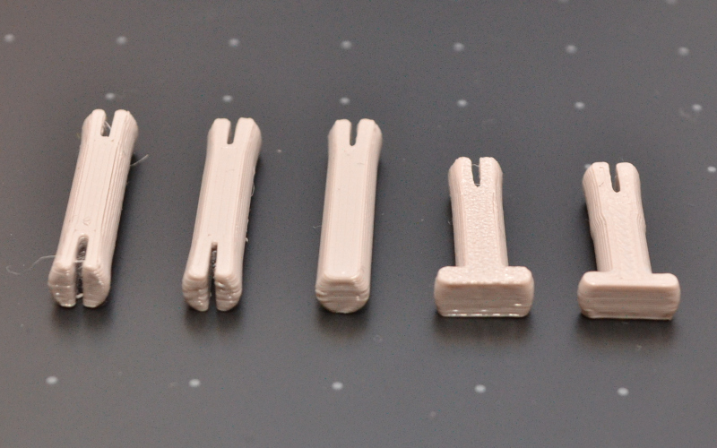
From left: pin, shaft with forks on both ends, shaft with a single fork, t-shaft, t-shaft with pin.
Other Shafts
Some motors have driveshafts in the shape of a plus sign '+'. For these purposes, the construction kit provides adapters or wheels that include a hole specifically designed for such driveshafts or shafts.
Instead of the standard printed shafts, you can also use round rods with a diameter of 4.5 mm. Ideally, these should fit into the kit’s holes in such a way that they do not wobble and do not create resistance when turning. However, round rods with a diameter of 4 mm can also be used.
Wheels
The range of wheels in the construction kit is truly huge. Most wheels sizes correspond to multiples of eight. In the kit you will find:
- smooth wheels
- wheels for O-rings
- gear wheels
- wheels with off-road tread
- wheels with large teeth for track chain
- train wheels designed for rails
- omni-wheels
Wheels for O-rings are adapted so that they can be complemented by sealing O-rings. Because these are made of rubber, they provide better grip on a smooth surface and function like tires.
Wheels can further be divided into two categories:
- with a hole for a shaft
- with a hole for an adapter
Wheels with a hole for a shaft have the proper hole in their center into which the shaft is inserted directly. Therefore, some wheels even have holes for shafts with a plus-shaped profile. This applies especially to smaller wheels. Such wheels may also feature holes for the use of M3 screws to secure them to the shafts.
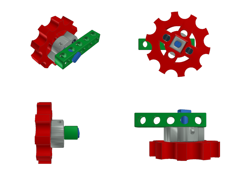
Wheels with a hole for an adapter have an 8 mm x 8 mm hole in the center, so that the base piece of the construction kit (beam) can be inserted into the hole. The hole is used for attaching adapters, which are then secured to the wheel using two pins.
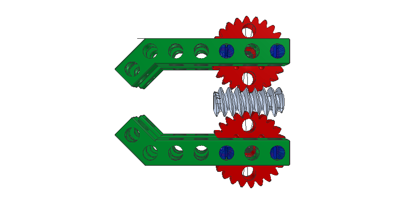
Shafts are inserted correctly, with the proper orientation, into BitBeam wheels and adapters.
Adapters
Adapters serve to attach especially larger wheels to shafts and motor driveshafts of various sizes. Therefore, the construction kit offers several adapters in different dimensions, primarily for the most common linear and stepper motors.
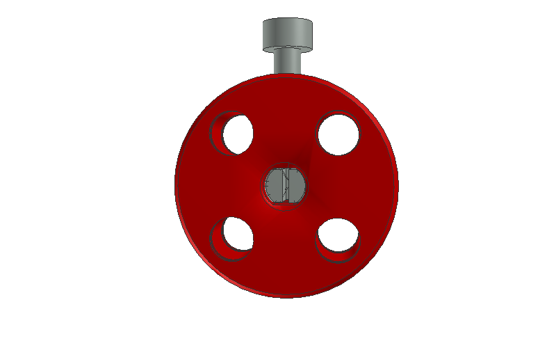
Adapters come in two sizes. The classic version is one and a half pieces high. Its first part consists of a wider cylinder into which M3 nuts can be inserted. These serve to secure the adapter more firmly to shafts and driveshafts. The piece then includes a square protrusion that is designed to fit into the central hole of larger wheels. The adapter is subsequently secured to the wheel using two pins or M4 screws.
The slimmer variant performs its function in the same way, but it is only one piece high and has thinner wings for attachment to the wheel. It includes holes for M3 screws, which grip only in the plastic. The attachment to the wheel is also achieved using pins or M4 screws.
The adapter is attached to the wheel and then secured to the kit using a t-shaft.